Typical Creo Elements models have many inside or re-entrant corners. In the real world you could not build a part with perfect sharp inside corners. There will always be some radius resulting from the tooling used to make the part. Sometimes fillets are left off the CAD parts and are specified in the drawing notes. In the FEA world re-entrant corners are a bad thing. These represent an infinite change in stiffness inside the part, which will result in an infinite stress concentration. The MPA convergence algorithm will not converge on infinity and the SPA algorithm will ignore any elements touching a re-entrant corner during its error estimation. The resulting stress convergence plot will be a line that continues to increase without ever starting to reach an asymptote.
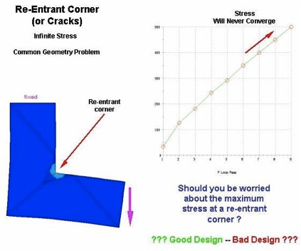
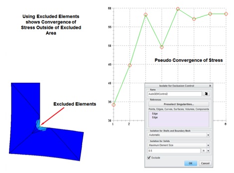
If this is a problem in your Creo Simulate model you should probably ask the question “Is this a good design having the highest stress in the model at a re-entrant corner?” The answer may be ‘yes’ if the material is ductile and fatigue loading is not an issue. If this is true and you are planning to ignore this stress just add a small fillet to prevent a convergence problem or use the ‘Isolate for Exclusion’ option under Mesh Control. Otherwise you may want to rethink the design.
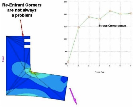
Theoretically re-entrant corners should always cause a problem for convergence, however, due to the coarseness of the error estimation process re-entrant corner convergence problems generally only show up in higher stress areas of the model.
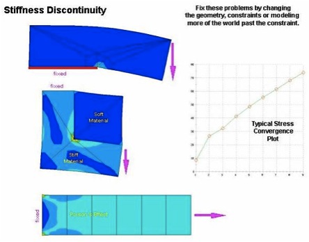
Other similar stiffness discontinuity problems are shown below.